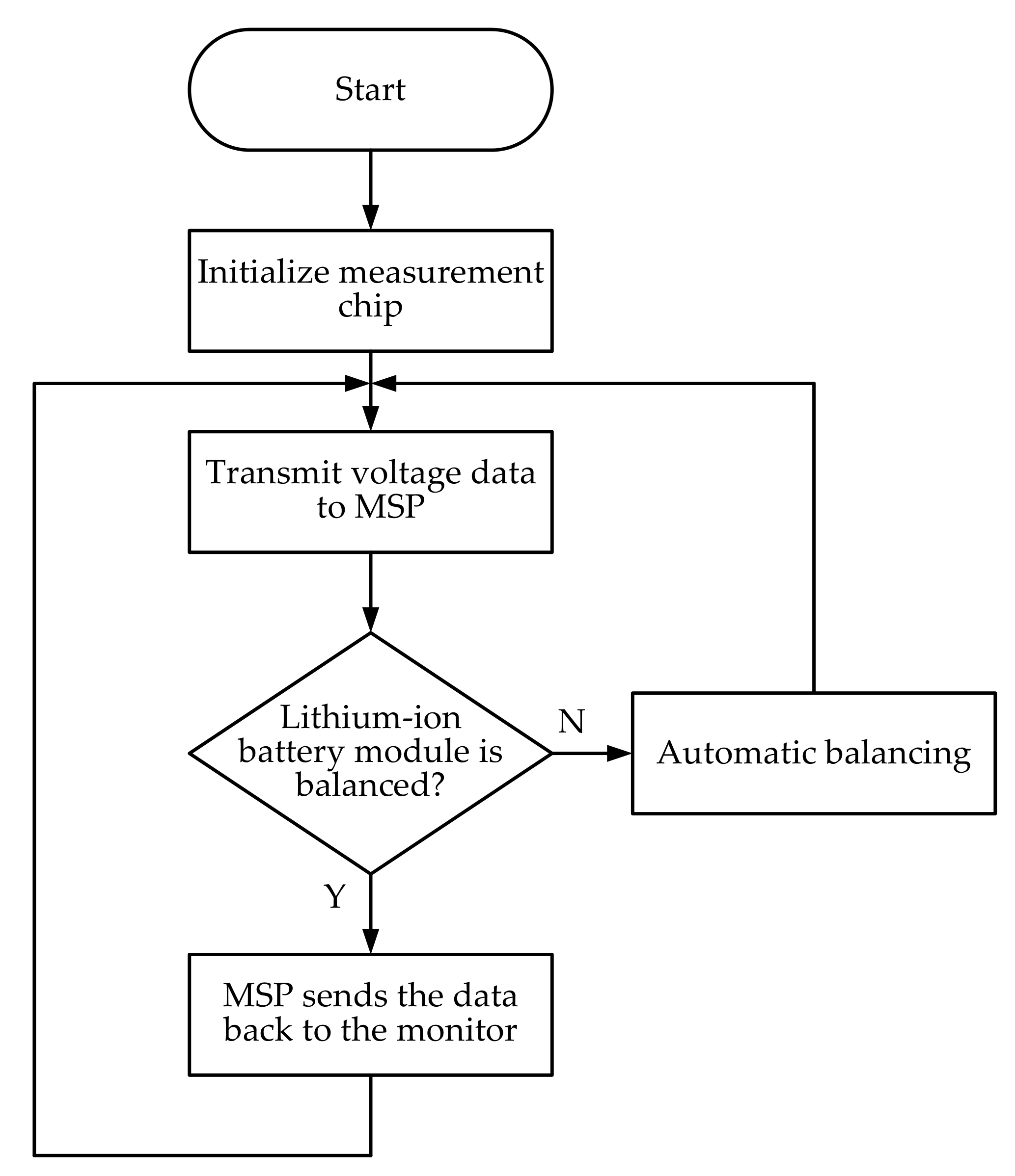
High Voltage Battery Management System BMS based on NXP Solution Circuit Diagram This is where a Battery Management System (BMS) becomes crucial. A well-designed BMS circuit can prevent overcharging, over-discharging, and short circuits, while also balancing individual cells in a battery pack. ensuring that the charging process is safe and consistent for the entire battery pack. Circuit Design for 3S Configuration 1. Learn the high-level basics of what role battery management systems (BMSs) play in power design and what components are necessary for their basic functions. Nowadays, Li-ion batteries reign supreme, with energy densities up to 265 Wh/kg.

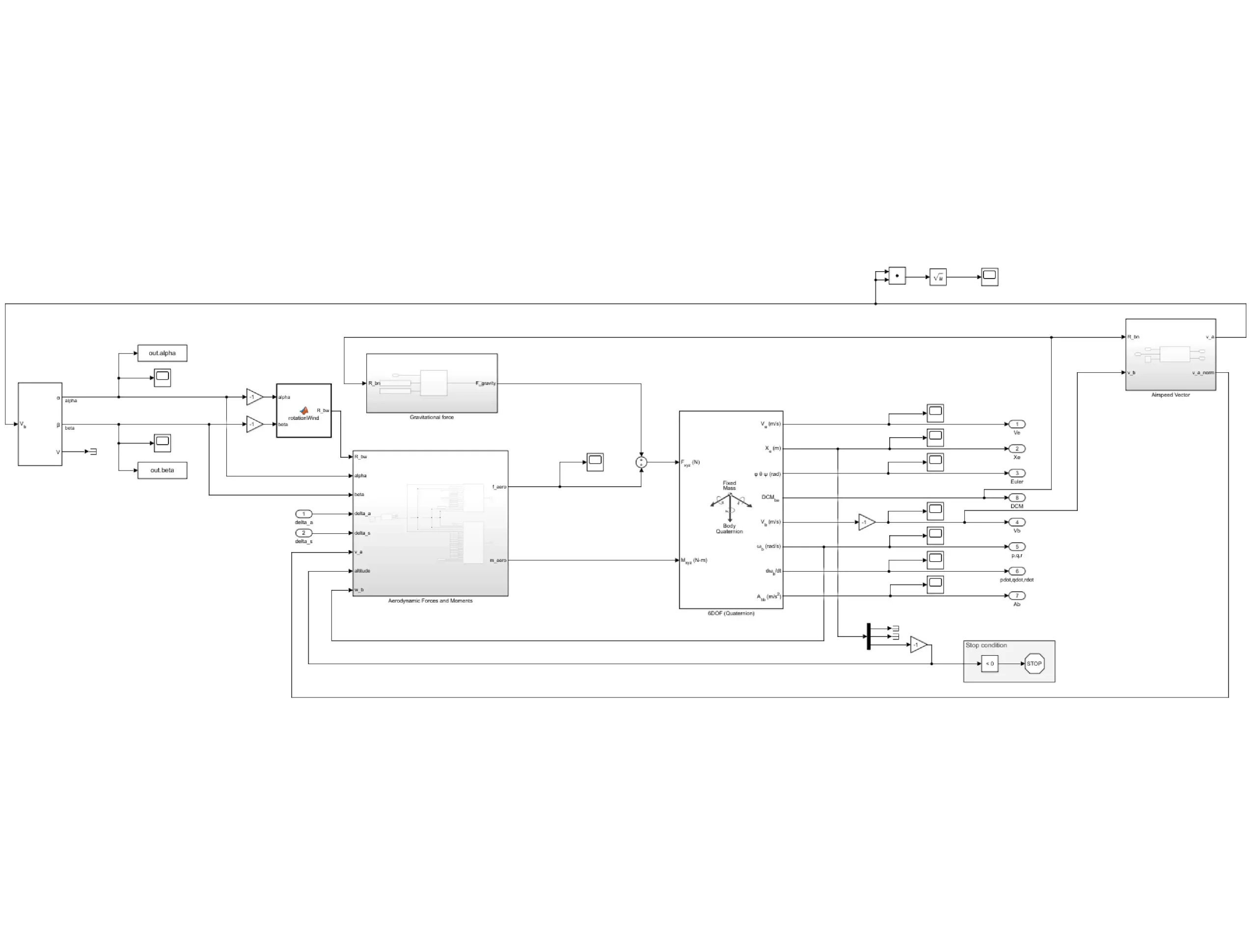
connecting the battery system to the power source and load. Simscape Electrical, an add-on product for Simulink, provides complete libraries of the active and passive electrical components needed to assemble a complete battery system circuit, such as the analog front end for cell balancing. The charging source can consist of a DC supply, such
PDF How to Design a Battery Management System (BMS) By Tomas Hudson ... Circuit Diagram
A comprehensive Battery Management System (BMS) design comprises various core components that work together to manage and monitor the battery. This section delves into the function of the Analog Front-End (AFE) in BMS design , the role of the Microcontroller (MCU) , and the importance of the Fuel Gauge in battery management. Improper charging can cause lithium-ion batteries to swell or even explode. Deep discharge can also lead to battery failure. An ideal lithium-ion battery charger should have voltage and current stabilization as well as a balancing system for battery banks. The voltage of a fully charged lithium-ion cell is 4.2 Volts.
BMS (Battery Management System) is a comprehensive system that includes monitoring, control, and protection functions for battery packs, while a battery protection board typically refers to a simpler circuit that provides basic protection functions such as overcharge and over-discharge protection for individual cells or small battery packs.

PDF Developing Battery Management Systems with Simulink and Model Circuit Diagram
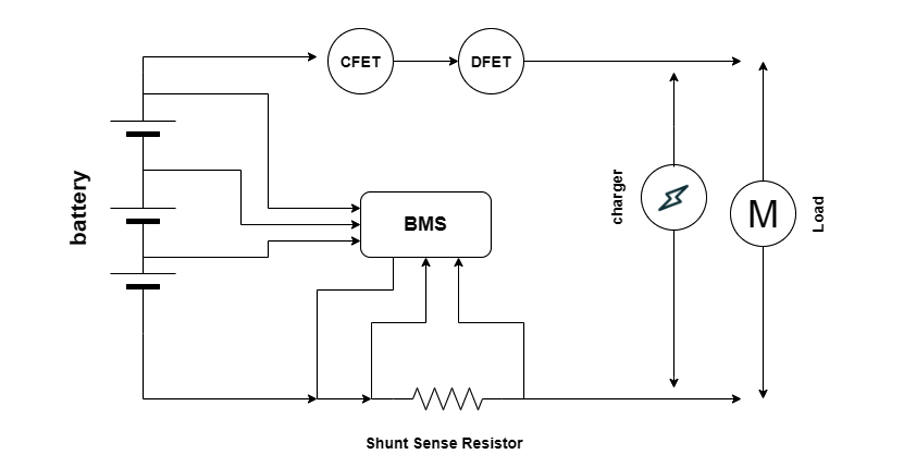
Figure 1: BMS Architecture. The AFE provides the MCU and fuel gauge with voltage, temperature, and current readings from the battery. Since the AFE is physically closest to the battery, it is recommended that the AFE also controls the circuit breakers, which disconnect the battery from the rest of the system if any faults are triggered. Future Trends in Battery Management System Circuit Design. In recent years, the development of battery technology has become crucial in various industries, such as electric vehicles, renewable energy systems, and portable devices. The efficiency and performance of these batteries depend significantly on the proper management and control of